The properties of Sn–Zn–Al–La fusible alloy for mitigation devices of solid propellant rocket motors
Release time:2025/06/09 13:47:01
Introduction
Solid propellant rocket motors have the advantages of large thrust, high reliability, convenient launch, and low maintenance cost. They are increasingly used in many fields, such as satellite launch, manned spaceflight, and deep space exploration . The safety of solid propellant rocket motors, especially thermal safety, has attracted much attention. At present, many studies have shown that the application of mitigation devices can significantly improve the safety of rocket motor case against accidental thermal stimuli such as fires or abnormal high temperatures . Fusible alloys can be used in the mitigation devices of the rocket motor case because of their heat sensitivity. Its working mechanism is that the ventilation is established through mitigation devices to weaken the confinement strength of the propellant to avoid the deflagration to detonation transition . That is, with increasing ambient temperature, the propellant continues to decompose and produce gas, which increases the internal pressure of the case. Meanwhile, the mechanical strength of the fusible alloy at high temperature decreases. Then, the mitigation devices of fusible alloy fail under ambient temperature and internal pressure . The ventilation of the rocket motor case is opened before the violent detonation of the propellant so that the propellant has a relatively mild combustion reaction. This technique reduces the response level of the solid motor and enables the motor to meet safety requirements. At the same time, its mechanical properties meet the strength requirements of the rocket motor case in the ambient temperature range of −50 °C to −70 °C, which can ensure the motor works properly .
At present, Sn–Pb and Sn–Bi and Sn–Zn alloys can be used in the mitigation devices of solid rocket motor case. The Sn–Pb fusible alloy has great toxicity and cannot be applied in engineering . The Sn–Bi alloy has poor plasticity. Especially in high temperature, there will be serious coarsening and even brittleness . The eutectic alloy of the SnZn binary alloy is Sn9Zn, and the melting point is 198 °C. It has good mechanical properties, abundant resources, and a low price of raw materials and is nontoxic. However, the Sn9Zn alloy is prone to oxidation and has poor corrosion resistance. To solve the above problems, scholars at home and abroad have studied improving the performance of SnZn alloy by adding other metal elements, such as Bi, Ag, Al, La, and so on. However, the addition of Bi can lead to the enrichment and precipitation of Zn . Ag is also often used as the modified element to add Sn9Zn. After adding Ag to the Sn9Zn alloy, Ag–Zn intermetallic compound is formed, which improves the mechanical properties of the alloy. However, Ag is more expensive, and the cost is more expensive. In recent years, many studies have shown that the addition of Al can improve the oxidation resistance of Sn–Zn alloy and reduce the Zn-rich phase . Rare earth elements are added to Sn-based fusible alloys to improve their properties. It has been shown that adding the appropriate amount of La can improve the melting point and microstructure uniformity of Sn–Zn–Al-based solders . At present, the design and preparation of Sn–Zn fusible alloys and their application in the mitigation devices of solid motor shells have not been reported in the public literature .
In this paper, the design method of the fusible alloy for the rocket motor case was given, aiming at the safety requirements of ventilation under thermal stimulation and the requirements of environmental adaptability. The fusible alloy based on the Sn9Zn binary alloy with Al and La as modified elements was designed and prepared. Differential scanning calorimetry (DSC), metallographic analysis, scanning electron microscopy (SEM), energy dispersive spectroscopy (EDS), tensile testing and fracture analysis were used to study the effect of Al and La elements on the microstructure, melting characteristics, and mechanical properties of the Sn9Zn alloy. Whether the fusible diaphragm can effectively relieve pressure was investigated by the hydrostatic pressure at high-temperature test.
Experimental
Alloy design
Generally, the working temperature of mitigation devices is related to the ignition temperature of the solid propellant charge, and the reaction temperature of the propellant in slow cook-off can be used as the design ground of fusible alloy. Three-component HTPB propellant (AP/Al/HTPB) has the advantages of stable combustion under low-pressure conditions, high energy release rate, good mechanical properties, and long-term storage stability. It is currently the most widely used composite propellant. The results show that the response temperature of the typical three-component HTPB propellant is approximately 235 °C. Strickland et al. pointed out that the working temperature of the ventilation should be more than 60 °C lower than the response temperature of the composite propellant in slow cook-off to effectively suppress the combustion to detonation of the composite propellant. In other words, the working temperature of the mitigation devices should be approximately 175 °C. Therefore, the melting point of the fusible alloy for the mitigation devices should be below the response temperature of the propellant in slow cook-off, and the mechanical strength of the fusible alloy decreases significantly at 175 °C to ensure that the mitigation devices will be destroyed under the internal pressure at this temperature.
The melting point of the Sn–Zn binary alloy system is 198.5 °C, which basically meets the design requirements of mitigation devices. At the same time, the fusible alloy should also meet the requirements of environmental adaptability. That is, it has good mechanical properties at −50 °C–70 °C. According to the literature, Al mainly exists in the solid solution state of the Al–Sn alloy, but the solution Al in Sn is very small. With the increasing amount of Al, the solubility of Al in Sn gradually reaches saturation, and Al will gradually precipitate out in the form of elemental. Al mainly exists in the solid solution state in the Al–Zn alloy, and the solution of Al in Sn is less than that in Zn. The addition of a small amount of Al will reduce the Zn-rich phase, which can optimize the mechanical properties of the alloy. The addition of a small amount of rare earth element La mainly exists in two forms: one kind of rare earth element La is solidly dissolved in the matrix, which has the effect of solid solution strengthening; the second kind of rare earth element La concentrates on the grain boundary, which increases the deformation resistance, promotes the increment of dislocation, and improves the strength. The mechanical properties of the alloy can be improved by adding Al and La as modification elements, but the amount of addition needs further experimental determination.
Based on the above analysis, Sn–Zn–Al–La alloys with Al concentrations ranging from 0 to 30 wt% and La concentrations ranging from 0 to 0.3 wt% were designed. The designed components are shown in Table 1
Table 1 Designed components.
Test codes
Sn/(wt%)
Zn/(wt%)
Al/(wt%)
La/(wt%)
1
91
9
0
0
2
90.1
8.9
0.8
0.2
3
88.1
8.7
3
0.2
4
81.6
8.1
10
0.3
5
72.5
7.2
20
0.3
6
63.4
6.3
30
0.3
Preparation
Prue Sn, Zn, Al and Al–20La with of 99.9 wt% were weighed according to the designed components in Table 1. The solidus of Al–20La is 640°Cand the liquidus is 788 °C. In the temperature range, Zn volatilizes obviously. Therefore, Sn, Al and Al–20La are melted in a graphite crucible at 800–850 °C to form the Sn–Al–La alloy. Then, the Sn–Al–La alloy and Zn were melted in a graphite crucible at 600–650 °C. In the melting process, a stainless steel rod was stirred every 10 min, and the temperature was kept for 30–40 min after all metals were melted. Finally, the molten alloys were cast in a copper mold, cooled in a water bath, and solidified to form. The casting after casting was a cuboid. Each alloy was repeatedly dissolved three times.
Property test
Melting point
The melting characteristics of the Sn–Zn–Al–La alloys were studied by differential scanning calorimetry (DSC). The alloy analyzed by DSC was 2 mg alloy powder, which was put into a corundum crucible container. The temperature range of the test was 50–850 °C, and the heating rate was 5 °C/min in a nitrogen atmosphere.
Microstructure and element distribution
The cast Sn–Zn–Al–La alloys were inlaid, ground, mechanically polished, and subjected to other steps to prepare metallographic samples, and the metallographic samples were eroded. Then, the metallographic samples were observed and photographed under a metallographic microscope. The distribution of elements in the prepared metallographic alloys was observed by surface scanning electron microscopy (SEM) and energy dispersive spectrometry (EDS).
Mechanical property
The Sn–Zn–Al–La cuboid castings were made into bone-shaped tensile specimens. The tensile properties of the Sn–Zn–Al–La alloys were measured by an electronic universal testing machine at −50 °C, 25 °C, 70 °C, 125 °C, and 175 °C at a strain rate of 3 mm/min. After the tensile experiment, SEM and EDS were performed on the fracture of the alloy to analyze the fracture mode and fracture mechanism. A schematic illustration of the tensile test specimen is shown inFig. 1
Fig. 1
Schematic illustration of the tensile test specimen.
Hydrostatic pressure at high-temperature test
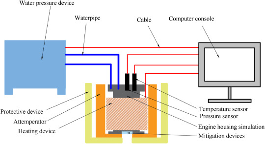
Using the hydraulic press to pressurize and heating belt to heat up simulated the high-temperature and high-pressure environment of the rocket motor case when the motor was subjected to accidental thermal stimulus to cause the propellant ignition reaction. The experimental device is shown in Fig. 2
Fig. 2
Schematic diagram of the hydrostatic pressure at high-temperature test.
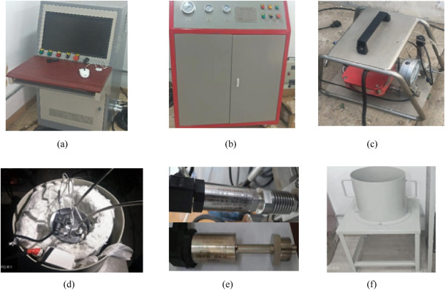
which mainly consists of the water pressure device, heating device, temperature sensor, pressure sensor, rocket motor case simulation, protective device, attemperator, mitigation devices and computer console. The maximum pressure boost rate is 12 MPa/min, the working pressure range is 20–100 MPa, and the maximum heating rate is 15 °C/min. Operating temperature up to 300 °C. Fig. 3
Fig. 3 Physical map of the hydrostatic pressure at high-temperature test.
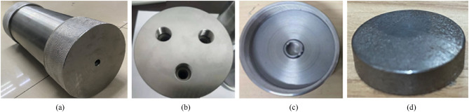
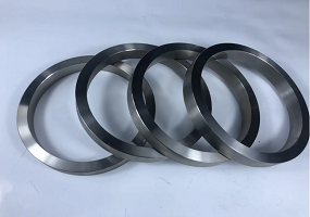
The purpose of the hydrostatic pressure during the high-temperature test is to test the actual bearing capacity and pressure-relief effect of the fusible alloy at the set high temperature. The fusible alloy was made into the diaphragm, which was assembled in the rocket motor case simulation to conduct the hydrostatic pressure at high-temperature test and the comparative experiment. Fig. 4
Fig. 4
Physical maps of the rocket motor case simulator and fusible diaphragm.
shows the physical map of the rocket motor case simulation and the fusible diaphragm, in which the thickness of the diaphragm is 3 mm and the vent is 10 mm. Fig. 4(a) is the rocket motor case simulation. Fig. 4(b) shows the upper end cover of the rocket motor case simulation, which has three holes, namely, the water inlet, the water outlet and the pressure measuring hole. Fig. 4(c) is the lower end cover. The fusible diaphragm, as shown in Fig. 4(d), is fixed on the lower end cover of the rocket motor case simulator through a metal pressure ring. The real-time data of the hydrostatic pressure at high-temperature test is recorded through the computer console. In the first stage, the airtightness was tested, and the pressure was set at 2 MPa. Then, the rocket motor case simulation was heated at 3 °C/min. The highest temperature was set at 175 °C, and the pressure was continued to be set at 40 MPa.
Results
Melting point
The working temperature of mitigation devices is related to the melting point of the fusible material. The melting temperature of the Sn–Zn–Al–La alloys is shown in Table 2
Table 2 Melting temperature
Composition/(wt%)
Melting temperature/°C
Sn9Zn
201.3
Sn9Zn-0.8Al0·2La
206.2
Sn9Zn–3Al0·2La
205.6
Sn9Zn–10Al0·3La
198.9
Sn9Zn–20Al0·3La
199.6
Sn9Zn–30Al0·3La
198.4
The melting temperature of the Sn9Zn alloy is 201.3 °C, which is not much different from the 198 °C in the literature. Compared with the Sn9Zn alloy, the melting temperature of the Sn9Zn-0.8Al0·2La alloy and the Sn9Zn–3Al0·2La alloy is increased by adding a small amount of Al and La, but the change is not significant. The melting temperatures of the Sn9Zn–10Al0·3La alloy, the Sn9Zn–20Al0·3La alloy and the Sn9Zn–30Al0·3La alloy are lower than that of Sn9Zn, but the change is not obvious. The results show that the addition of Al and La has little effect on the melting temperature of Sn9Zn.
Microstructure
Fig. 5
Metallographs of the Sn–9Zn alloys with Al and La.
shows the metallographic structure of the Sn–Zn–Al–La alloys with different Al contents and La contents to reveal the influence of Al and La on the microstructure.
Fig. 5
(a) shows the microstructure of the Sn9Zn eutectic alloy, which is composed of many black Zn-rich precipitates distributed in the gray β - Sn matrix. The Sn9Zn alloy shown in
Fig. 5
is consistent with that in the literature. From
Fig. 5
(b)–
Fig. 5
(f), with increasing Al content and La content, black Zn-rich precipitates distributed in the gray β-Sn matrix gradually decrease. In
Fig. 5
(b) and
Fig. 5
(c), the mass fraction of La is 0.2%. With increasing Al content, the proportion of black dendritic structures in the alloy increases significantly. The elemental mapping shows that the black dendritic structure is Al and a small amount of Zn dissolved in Al. As shown in
Fig.5
(b)–
Fig. 5
(f), as the Al content increases, the black dendritic structure first increases. When the Al content increased to 10%, the black dendritic structure gradually decreased. When the Al content increased to 30%, the black dendritic structures disappeared, and a silver-white structure with obvious grain boundaries was formed.
Elemental mapping
3.3
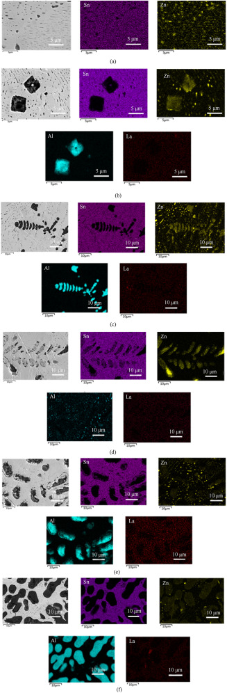
Fig. 6
Electron micrograph and element maps of the Sn–9Zn alloys with Al and La.
(a) shows the SEM micrograph and element map of the Sn9Zn alloy. The part of Zn and Sn formed the eutectic structure, and the other part existed as Zn-rich phase. The Zn-rich phase is dark needle-like and round. The microstructure is consistent with that of the Sn9Zn alloy in the literature. Fig. 6(b) shows the SEM micrograph and element maps of the Sn9Zn-0.8Al0·2La alloy. In the element maps, La is uniformly distributed in the alloy as small dots. Al is distributed in bulk with obvious grain boundaries. Zn also exists in Al-containing structures. Fig. 6(c) shows the SEM micrograph and element maps of the Sn9Zn–3Al0·2La alloy. In the microstructure, La in spots is uniformly distributed in the alloy, and the Al distribution has obvious grain boundaries. The part of Zn exists in the Zn-rich phase, and the other part existed in the Al. Fig. 6(d) shows the element maps of the Sn9Zn–10Al0·3La alloy. The SEM micrograph shows that of 3% Al and 0.3% La, La is distributed uniformly in dots, and Al is an obvious grain boundary. The SEM micrographs and element maps of the Sn9Zn–20Al-0.3La alloy are shown in Fig. 6(e). Fig. 6(f) shows the SEM micrograph and element maps of the Sn9Zn–30Al0·3La alloy, such as the addition of 20% Al and 0.3% La. With the addition of Al, an increasing amount of Al precipitates. The results show that the addition of a small amount of Al can reduce the aggregation of the Zn-rich phase in the alloy. When the addition amount of Al exceeds 10%, an increasing amount of Al precipitates out in the alloy structure in an elliptical shape, forming the aggregation of Al and obvious grain boundaries. La is uniformly distributed in the alloy in a point shape.
Mechanical properties
Tensile properties
Fig. 7
Tensile stress-strain curves of the Sn–9Zn alloys with Al and La at different temperatures.
shows the tensile stress–strain curves of the Sn–Zn–Al–La alloys with different Al contents at −50 °C, 25 °C, 70 °C and 175 °C. At −50 °C, the yield phenomenon of the alloys except the Sn9Zn–30Al0·3La alloy is obvious, and the fracture modes of these alloys are characterized by ductile fracture. The tensile strength of the Sn9Zn–3Al0·2La alloy is the highest, which is 40% higher than that of the Sn9Zn eutectic alloy. At 25 °C, the yield phenomenon of the alloy except the Sn9Zn–3Al0·2La alloy is obvious, and the fracture modes of these alloys are characterized by ductile fracture. The tensile strength of the Sn9Zn-0.8Al0·2La alloy is the highest, which is 48% higher than that of the Sn9Zn eutectic alloy. At 70 °C, the yield phenomenon of the alloys is obvious, and the fracture modes of these alloys are characterized by ductile fracture. The tensile strength of the Sn9Zn-0.8Al0·2La and Sn9Zn–3Al0·2La alloys is better than that of other alloys, and the tensile strength of the Sn9Zn alloy is 88% and 55% higher than that of the Sn9Zn alloy at 70 °C, respectively. At 175 °C, the tensile strength of the Sn9Zn–3Al0·2La alloy is the lowest, and the mechanical properties of the Sn9Zn-0.8Al0·2La and Sn9Zn–3Al0·2La alloys are significantly improved at −50 °C–70 °C. When the working temperature of the ventilation is 175 °C the mechanical properties of the alloy decrease sharply, and the ventilation is opened in time to meet the design requirements.
Tensile fracture
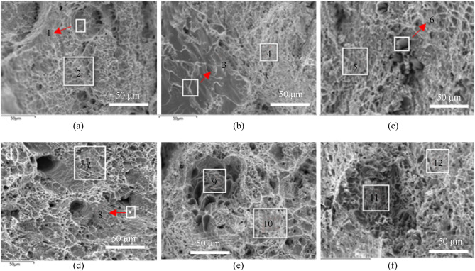
The tensile fracture of Sn–Zn–Al–La at 25 °C was analyzed by scanning electron microscopy ( Fig. 8
Fig. 8
Fractographies of the Sn–9Zn alloys with Al and la.
).Fig. 8 (a) shows the fractography of eutectic alloy Sn9Zn. There are obvious cleavage steps, tearing edges and dimples in the fracture. EDS analysis results are shown inTable 3
Table 3 EDS analysis results of fractographies
No.
Element mass fraction
Sn
Zn
Al
1
89.5
10.5
–
2
91.3
8.7
–
3
14.5
79.6
–
4
87.5
9.3
0.3
5
85.5
8.2
0.4
6
84
8.3
7.7
7
76.8
9.4
13.9
8
78.8
19.9
1.3
9
26.3
10.4
63.3
10
84
8.3
7.7
11
17.4
14.6
68
12
11.1
81
7.8
No. 1 and 2 are the EDS analysis results of the fracture surface for the Sn9Zn eutectic alloy. No. 1 and 2 have a large amount of Sn and a small amount of Zn, with obvious dimples. The fracture mode of the Sn9Zn eutectic alloy is ductile fracture accompanied by local brittle fracture.Fig. 8 (b) shows the fracture of the Sn9Zn alloy with 0.8% Al and 0.2% La. Cleavage steps, tearing edges and dimples with obvious river patterns can be observed in the fracture. InTable 3 , Nos. 3 and 4 are the EDS analysis results of the fracture surface for the Sn9Zn-0.8Al0·2La alloy. No. 3 has a large amount of Zn, a small amount of Sn and a small amount of Al. There is a large amount of Sn and a small amount of Zn at 4. These results indicate that the higher the Zn content is, the more obvious the characteristics of brittle fracture.Fig. 8 (c) shows the fracture of the Sn9Zn–3Al0·2La alloy. There are obvious dimples in the fracture. InTable 3 , No. 5 and 6 are the E EDS analysis results of the fracture surface for the Sn9Zn–3Al0·2La alloy. There is a large amount of Sn, a small amount of Zn and a small amount of Al at Nos. 5 and 6. The addition of a small amount of Al weakens the characteristics of brittle fracture of the alloy.Fig. 8 (d) shows the fracture of the Sn9Zn–10Al0·3La alloy. There are obvious dimples in the fracture. InTable 3 , Nos. 7 and 8 are the EDS analysis results of the fracture surface. There are many Sn and small amounts of Zn and Al at Nos. 7 and 8. The fracture mode is still ductile fracture.Fig. 8 (e) shows the fracture of the Sn9Zn–20Al0·3La alloy. There are obvious dimples and obvious grains in the fracture. No. 9 and 10 inTable 3 are the EDS analysis results of the fracture surface. At No. 9, there is a large amount of Al and a small amount of Sn and Zn. There are many Sn and a small amount of Zn and Al at No. 10, indicating that the addition of much Al will lead to intergranular fracture of the alloy.Fig. 8 (f) shows the fracture of the Sn9Zn–20Al0·3La alloy. There are obvious dimples and obvious grains in the fracture. The area of intergranular fracture is enlarged. It can also be seen from the EDS analysis results at No. 11 that a large amount of Al will lead to intergranular fracture of the alloy.
Pressure relief
As mentioned above, the melting point of the fusible alloy should be below the response temperature of the propellant in slow cook-off. The mechanical strength of the fusible alloy is significantly reduced at 175 °C to ensure that the mitigation devices are opened in advance and that the pressure is effectively relieved. According to the DSC test results ( Table 2) and the mechanical properties test results of the alloys at 175 °C ( Table 4),
Table 4 Mechanical properties of the Sn–9Zn alloys with Al and La.
Fusible alloy
The proportion of mechanical property improvement than the Sn9Zn alloy
The proportion of mechanical property decreasing than at 25 °C
−50 °C
25 °C
70 °C
175 °C
Sn9Zn-0.8Al0·2La
36.2%
48.4%
55%
88%
Sn9Zn–3Al0·2La
40%
48.4%
55%
–
Sn9Zn–10Al0·2La
10%
26.5%
17.9%
80%
Sn9Zn–20Al0·2La
20.1%
26.7%
35.2%
89%
Sn9Zn–30Al0·2La
−40%
34.8%
27.5%
76.9%
the melting points of all alloys were lower than the response temperature of the three-component HTPB propellant in slow cook-off, and the tensile strength of all alloys lost more than 70% at 175 °C. From the analysis of environmental adaptability, the tensile properties of the alloys with Al and La are higher than those of the Sn9Zn alloy at −50 °C–70 °C, but the addition of a large amount of Al will cause the aggregation of Al. Obvious grain boundaries will be formed in the alloys, and the alloys will recrystallize and fracture. The mechanical properties of the Sn9Zn-0.8Al0·2La alloy and the Sn9Zn-0.8Al0·2La alloy were improved most significantly at −50 °C–70 °C, and no crystallization fracture occurred. Moreover, the tensile strength of the Sn9Zn-0.8Al0·2La alloy and the Sn9Zn-0.8Al0·2La alloy lose more than 70% at 175 °C, which can not only effectively relieve pressure but also meet the requirements of environmental adaptability. Therefore, the Sn9Zn–3Al0·2La alloy and the Sn9Zn-0.8Al0·2La alloy were selected for the mitigation devices in this paper, and the diaphragm made of these two alloys was tested by the hydrostatic pressure at high-temperature test.
The hydrostatic pressure at high-temperature test included three stages. In the first stage of the test, the rocket motor case and the fusible diaphragm had good airtightness without deformation or damage when the internal pressure of the rocket motor case was 2 MPa. The second stage was to maintain pressure and keep heating. This stage ended when the water temperature reached 175 °C, and the pressure inside the shell was 2 MPa. In this process, pressure relief was required to counteract the increase in pressure due to heating water. The third stage was to hold high temperature and gradually pressurize up to 40 MPa until the diaphragm broke. When the pressure reached the burst pressure of the test sample, the pressure inside the shell was released instantly, the water vaporized instantly, and the temperature inside the shell also decreased rapidly. The pressure curve and temperature curve of the third stage are shown in Fig. 9
Fig. 9
Pressure curve and temperature curve of the hydrostatic pressure at high-temperature test.
The rocket motor case simulation with a 3 mm thickness of the Sn9Zn-0.8Al0·2La alloy has a burst pressure of 19.88 MPa, and the rocket motor case simulation with a 3 mm thickness of the Sn9Zn–3Al0·2La alloy has a burst pressure of 21.21 MPa. The temperature of the fusible alloy diaphragm for Sn9Zn–3Al0·2La and Sn9Zn-0.8Al0·2La were 161.3 °C and 162 °C respectively when they broke. The diaphragm and the rocket motor case simulation after the hydrostatic pressure in the high-temperature test are shown in Fig. 10
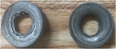
Fig. 10
The fusible diaphragms after the hydrostatic pressure at high-temperature test.
and Fig. 11
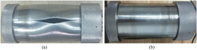
Fig. 11
The rocket motor case simulation after the hydrostatic pressure at high-temperature test.
respectively. By observing the experimental remains, the simulated rocket motor case without the fusible diaphragm had undergone obvious deformation at 175 °C, and the end cover could not be removed. The rocket motor case simulator with the fusible diaphragm remains intact, and the end cover can be removed. By assembling the fusible diaphragm on the rocket motor case simulator, the constraint strength of the rocket motor case simulator was reduced by nearly 50% at 175 °C. The results show that the diaphragm can ventilation in advance under a certain temperature environment and internal pressure and can be used in the design of mitigation devices.
Conclusions
(1)The addition of Al and La has little influence on the melting point of the Sn9Zn fusible alloy, and the melting point of the fusible alloy is lower than the response temperature of the propellant in slow cook-off, meeting the working temperature requirements of ventilation.
Metallographic analysis, energy spectrum analysis, tensile test and fracture analysis show that the addition of Al will reduce the Zn-rich phase, and the addition of La will refine the grain. The tensile properties of the alloys with Al and La at −50 °C–70 °C are higher than those of Sn9Zn. However, the addition of a large amount of Al will lead to the aggregation of Al and the formation of obvious grain boundaries in the alloy. The alloy will undergo recrystallization fracture, so the addition of Al should not be too much, preferably not more than 10%. The mechanical properties of the Sn9Zn-0.8Al0·2La alloy and the Sn9Zn–3Al0·2La alloy were improved most significantly at −50 °C–70 °C, and no crystallization fracture occurred. Moreover, the tensile strength of the Sn9Zn-0.8Al0·2La alloy and the Sn9Zn-0.8Al0·2La alloy lose more than 70% at 175 °C, which can not only effectively relieve pressure but also meet the requirements of environmental adaptability.
The hydrostatic pressure during the high-temperature test was carried out on the simulated motor case with a 3 mm thick fusible diaphragm. When the ambient temperature was 175 °C, the burst pressures of the simulated motor case with the Sn9Zn-0.8Al0·2La alloy fusible diaphragm and the Sn9Zn–3Al0·2La alloy fusible diaphragm were 19.88 MPa and 20.21 MPa respectively. By assembling the fusible diaphragm in the rocket motor case, the burst pressure of the shell can be reduced by approximately 50%, which can be applied to the design of mitigation devices for fusible alloys.